




Detailed Basics of High Voltage Switchgear II
 May 05, 2026|
(I)Three Positions of Switchgear Trolley
Working Position
In this position, the circuit breaker is fully connected to the primary system. When closed, it conducts power to the outgoing lines under normal operating conditions.
Test Position
In the test position, the circuit breaker is isolated from the primary circuit, while the secondary plug remains connected. This allows closing and tripping operations, along with status indication, to be tested without affecting the load side. It is mainly used for functional testing and commissioning.
Maintenance Position
In the maintenance position, the circuit breaker is completely disconnected from both primary and secondary circuits. It is fully isolated from all power sources, ensuring a safe condition for inspection, maintenance, and servicing.
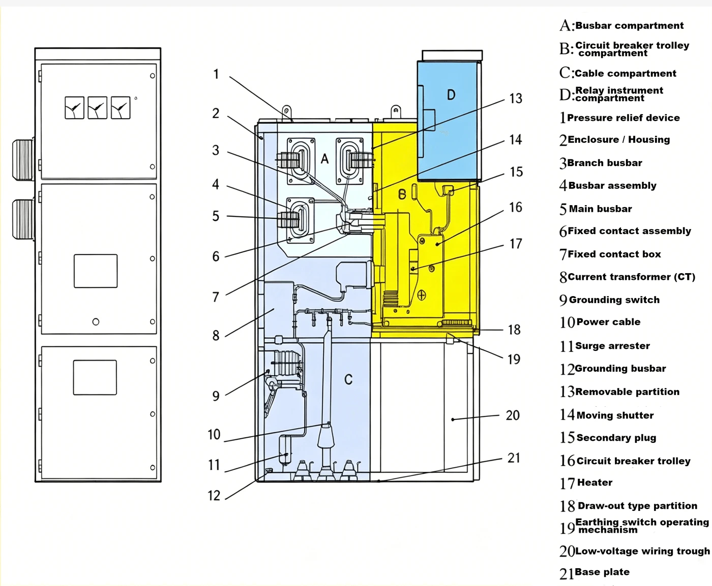
(II) Interlocking Devices of Switchgear
The switchgear is equipped with reliable interlocking mechanisms that comply with the "five-prevention" requirements, ensuring the safety of both operators and equipment.
a. Indicator buttons or selector switches are installed on the instrument compartment door to prevent incorrect closing or opening of the circuit breaker.
b. The circuit breaker can only be operated (closed or opened) when the trolley is in the test or working position. Once the breaker is closed, the trolley is locked in place and cannot be moved, preventing it from being pushed in or pulled out under load.
c. The breaker trolley can only be moved from the test/maintenance position to the working position when the earthing switch is in the open state. The earthing switch can only be closed when the breaker trolley is in the test/maintenance position. This prevents closing the earthing switch on a live circuit and avoids breaker operation when the earthing switch is closed.
d. When the earthing switch is open, the lower and rear cabinet doors remain locked, preventing personnel from accessing live compartments.
e. When the breaker trolley is in the test or working position without control voltage, only manual opening is allowed; closing operation is strictly prohibited.
f. When the breaker trolley is in the working position, the secondary plug is locked and cannot be withdrawn.
g. Electrical interlocking can be implemented between different switchgear cabinets.
h. The secondary connection between the switchgear and the breaker trolley is made via a manual secondary plug. The moving contacts of the secondary plug are connected to the breaker trolley through nylon corrugated hoses, while the fixed contact base is installed at the upper right of the trolley compartment. The secondary plug can only be inserted or withdrawn when the breaker trolley is in the test or disconnected position. When the trolley is in the working position, a mechanical interlock secures the plug to prevent disconnection.
(III)Five Preventive Functions of High-Voltage Switchgear
- Prevention of incorrect circuit breaker operation:
The circuit breaker can only be closed or opened when the breaker trolley is in the working or test position.
- Prevention of moving the breaker trolley under load:
The breaker trolley can only be inserted into or withdrawn from the working position when the circuit breaker is in the open state.
- Prevention of closing the earthing switch under live conditions:
The earthing switch can only be closed when the breaker trolley is in the test position.
- Prevention of energizing with the earthing switch closed:
The breaker trolley can only be moved to the working position for closing operation when the earthing switch is fully open.
- Prevention of accidental access to live compartments:
The rear door can only be opened when the breaker trolley is in the test position and the earthing switch is closed. For switchgear without an earthing switch, the rear door can only be unlocked and opened after the high-voltage power supply is disconnected and the electromagnetic door lock is released.
(IV)Mechanical Interlocking Functions
- The trolley can only be moved from the test/isolation position to the working position when both the earthing switch and the circuit breaker are in the open state. If the earthing switch is closed, the trolley cannot be moved to the working position.
- The earthing switch can only be operated when the trolley is in the test/isolation position or fully withdrawn.
- The circuit breaker can only be closed when the trolley is correctly positioned in the test/isolation position or the working position.
- When the breaker trolley is in the test/isolation or working position without control voltage, the circuit breaker can only be opened manually; closing is disabled.
- When the trolley is in the working position, the secondary plug is mechanically locked and cannot be withdrawn.
- The cable compartment door can only be opened when the earthing switch is closed; conversely, the earthing switch can only be operated after the cable compartment door is fully closed.
- After the trolley is fully withdrawn, the shutter can be secured with a padlock.
(V)Inspection and Maintenance
Daily Routine Inspection
- Ensure all meters display accurate readings and their surfaces are clean and free of dust.
- Check that the switch position indicators (open/closed) are accurate.
- Verify that all control switches on the high-voltage cabinet panel are in the proper positions.
- Confirm that the voltage and current levels are within the normal operating range.
- Inspect the operation of relay protection devices and check for any alarm signals.
- Check for any alarms on the high-voltage cabinet control panel.
- Ensure that all permanent grounding connections of panels and cabinets are secure and reliable.
- Check the operating condition of all equipment and components to ensure normal operation, with no abnormal noise or unusual odor.
Shutdown Maintenance Checklist
1. Cleaning
- Clean dust and dirt from both the interior and exterior of the cabinet.
2. Mechanical Inspection
- Check tightness of all bolts and connections at contact points.
- Inspect for signs of overheating or electrical discharge (burn marks, carbonization).
- Inspect and adjust the operating mechanism; verify proper function and polish where necessary.
3. Electrical Components
- Examine main circuit components for condition and integrity.
- Inspect circuit breaker contacts for wear and overheating.
- Check secondary wiring of relays and measuring instruments for looseness.
4. Protection & Interlocking
- Inspect performance and operation of the anti-misoperation interlocking device.
5. Insulation & Testing
- Measure insulation resistance of each outgoing circuit and all secondary circuits.
- Perform voltage withstand (hi-pot) tests on internal cabinet components.
6. Grounding
- Verify integrity and continuity of grounding connections and wires.
7. Auxiliary Systems
- Check condition and functionality of lighting devices.
8. Insulation Components
- Inspect supporting insulators, insulating pull rods, and breakdown fuses.
9. Vacuum Circuit Breaker
- Check the vacuum arc-extinguishing chamber.
- Inspect conductive connections for wear or looseness.