




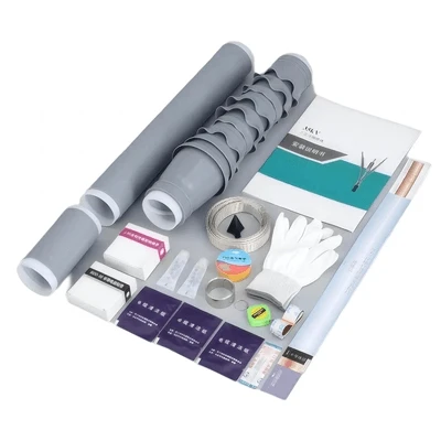

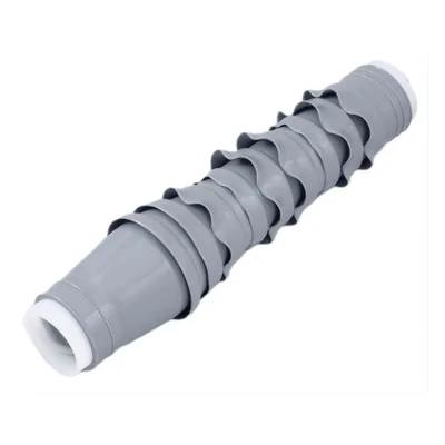
15-35kV Outdoor AIS Cable Termination Kits
The 15-35kV outdoor AIS cable termination kits are a premium, pre-expanded, rubber-based sleeve solution designed to securely seal and electrically terminate medium-voltage power cables (ranging from 15kV and 25kV up to 35kV) in demanding outdoor environments.

- Product Introduction
The 15-35kV outdoor AIS cable termination kits are a premium, pre-expanded, rubber-based sleeve solution designed to securely seal and electrically terminate medium-voltage power cables (ranging from 15kV and 25kV up to 35kV) in demanding outdoor environments. Engineered primarily for Air Insulated Switchgear (AIS) applications, The 15-35kV outdoor AIS cable termination kits facilitate a seamless, high-dielectric transition from the cable's internal insulation to the open air-effectively managing severe electrical stress while sealing out environmental elements on poles, pad-mounted equipment, and overhead line connections.
Core Performance Features
Core Performance Features
Advanced Environmental Resilience (Outdoor Rated)
UV Radiation Resistance: Excellent molecular stability under prolonged sunlight exposure to prevent chalking or material degradation.
Ozone & Anti-Tracking Protection: High ozone-resistant formulations eliminate the risk of surface cracking and carbon tracking under high electrical stress.
Moisture & Weatherproofing: Creates a continuous, high-compression hermetic seal that completely blocks heavy rain, humidity, and moisture ingress.
Thermal Flexibility: Maintains its elastomeric flexibility in extreme sub-zero cold and retains structural stability in high ambient heat.
Flame-Free Cold Shrink Technology: Features a simplified, heat-free installation matrix. The pre-stretched rubber sleeve is positioned over the prepared cable, and the internal plastic supporting core is unraveled and pulled out. The inherent elastic memory of the rubber causes it to shrink tightly and uniformly onto the cable profile, drastically reducing installation time and eliminating the need for open flames or specialized heating tools
Air Insulated Switchgear (AIS) Compliance
Engineered specifically for distribution grids where air serves as the primary insulating medium. The integrated rain skirts (sheds) optimize the external creepage distance and clearance profile, effectively mitigating flashover risks and meeting strict international clearance/strike distance standards.
Electrical Parameters
| Parameter | Standard Value 15kV | Standard Value 35kV | Explanation & Standard Reference(15 kV) |
|---|---|---|---|
| Rated System Voltage (U) | 15 kV | 35 kV | The nominal voltage level of the system. |
| Maximum System Voltage (Uₘ) | 17.5 kV | 40.5 kV | The maximum RMS line voltage the equipment can operate under continuously. This is the core basis for equipment classification. |
| Rated Voltage (U₀) | 8.7 kV | 26 kV | The rated power-frequency voltage between conductor and earth or metallic screen for which the cable is designed. |
| Rated Power Frequency Withstand Voltage (1 min) | 45 kV (AC) | 95/105 kV(AC) | The termination shall not flash over or break down when this AC voltage (RMS) is applied for 1 minute. This is a common requirement per IEEE 48 and GB standards. |
| Rated Lightning Impulse Withstand Voltage (BIL) | 95 kV or 110 kV | 200 kV or 250 kV | The termination shall not flash over or break down when subjected to 10 positive and 10 negative impulses of the standard lightning wave (1.2/50 μs). 110kV is a common higher-performance indicator. |
| Partial Discharge Level (PD) | ≤ 10 pC @ 13 kV (1.5U₀) | ≤ 10 pC @ 39 kV | The partial discharge magnitude shall not exceed 10 picoCoulombs at 1.5 times the rated phase voltage. This is a key indicator of perfect insulation manufacturing. |
| Creepage Distance | ≥ 560 mm (Common value) | ≥ 1050 mm (Common value) | Calculated based on the Specific Creepage Distance requirement. For Pollution Level IV (Heavy pollution), calculated as ≥31 mm/kV (Uₘ): 17.5kV * 31 mm/kV ≈ 542.5 mm. Actual product values commonly range from 560mm to 800mm. |
| Visible Corona Level | No visible corona @ 1.1 * Uₘ (19.25 kV) | No visible corona @ 1.1 * Uₘ (19.25 kV) | No visible corona should be observed with the naked eye under night-time or dark conditions at 1.1 times the maximum system voltage. |
| Shield Rated Withstand Current (Short-circuit) | Typically 20 kA, 2s or 25 kA, 1s | Typically 20 kA, 2s or 40 kA, 1s | The short-circuit current magnitude and duration that the grounding braid and connections can withstand. Must be coordinated with system protection. |
| External Insulation Level (Dry/Wet) | Power Frequency Withstand: approx. 40 kV (dry) / 35 kV (wet) | Power Frequency Withstand: approx. 85 kV (dry) / 65 kV (wet) | Tests the insulation performance of the external weather sheds. Wet withstand voltage simulates performance under heavy rain conditions. |
Differences from Indoor Terminations
| Feature | Outdoor Termination | Indoor Termination |
|---|---|---|
| Weather Sheds | Yes. Long, multiple sheds to increase the surface creepage path, preventing flashover in wet or contaminated conditions. | No. Smooth or short-shed design, as the environment is clean and dry. |
| Material | UV & Ozone Resistant ( Silicone). | Standard Rubber Compounds. May not be suitable for prolonged sun exposure. |
| Leakage Distance | Long. Designed to meet specific creepage distance requirements (e.g., >31 mm/kV). | Short. Only needs to accommodate clean, dry air. |
| Tracking Resistance | High. Withstands surface arcing caused by pollution. | Standard. Not a primary design concern. |
Installation Guide
| Step | Outdoor-Specific Focus |
|---|---|
| 1. Preparation & Cable Stripping | The precision of the strip is even more critical outdoors. Any error in the semiconductor or insulation length can misplace the stress control, leading to failure. |
| 2. Surface Preparation | Must be immaculately clean. Any dirt or moisture trapped during installation will cause tracking and failure over time. Use provided cleaner wipes thoroughly. |
| 3. Installing Grounding | Ensure the grounding braid connection is robust and corrosion-resistant. This is the path for fault current. |
| 4. Applying Sealing Mastic | This is a key weatherproofing step. Apply mastic exactly as instructed over shield cuts and grounding connections to create a smooth, sealed profile. |
| 5. Sliding on Termination Body | Ensure the termination is oriented correctly (usually with the larger shed section pointing upward). Align the stress control element with its position on the cable. |
| 6. Connecting the Conductor | Use a compression lug designed for outdoor use. Ensure the connection is tight and secure. |
| 7. Shrinking the Termination | Start pulling the support spiral from the BOTTOM (cable entry end). Pull evenly and watch as it shrinks uniformly up the cable. Ensure it is straight. |
| 8. Final Sealing & Grounding | Confirm the bottom skirt has shrunk tightly onto the cable jacket. Securely attach the grounding braid to the ground stake using a proper lug and corrosion-resistant hardware. |
| 9. Phase Identification | Apply phase markers near the lug end of the termination for clear identification. |
Advantages of 15-35kV Outdoor AIS Cable Termination Kits
Engineered Cold-Shrink Advantages: Leverages advanced elastomeric memory for a simplified, flame-free installation process. Eliminates the need for specialized heating tools or torches, ensuring a uniform, highly consistent radial pressure seal that mitigates installation errors.
Superior Hermetic Weatherproofing: Delivers an exceptional, high-compression barrier against moisture ingress-effectively neutralizing the primary root cause of medium-voltage outdoor termination failures.
Long-Term Environmental Durability: Formulated with premium UV-stabilized and ozone-resistant rubber compounds, ensuring an extended operational lifespan without material degradation, cracking, or chalking under direct, prolonged sunlight exposure.
High-Pollution Tracking Resistance: Designed with an optimized, extended creepage path via integrated rain sheds (skirts). This geometric design prevents surface tracking and suppresses flashover risks in dusty industrial zones, high-salinity coastal sectors, or heavily contaminated environments.
Grid Reliability & Zero Maintenance: When deployed according to standard installation guidelines, the system establishes a highly reliable, maintenance-free connection that reduces unplanned outages and minimizes long-term operational expenditures (OPEX).
Hot Tags: 15-35kv outdoor ais cable termination kits, China 15-35kv outdoor ais cable termination kits manufacturers, suppliers, factory, 66 110kV Dry Pluggable GIS Termination, cable termination kit, cold shrink sleeving, gis cable termination, gis termination kit, outdoor termination kit


