




Function, Working Principle and Capacity Calculation of Capacitor Banks
 Jun 04, 2026|
 1. Fundamental Working Principle
Most electrical loads in industrial power systems are inductive loads, such as asynchronous motors, transformers, welding machines, fluorescent lamps and electromagnets. Electrically, these loads can be regarded as a combination of resistance and inductance connected in series. As a result, the load current lags behind the voltage, generating a large amount of inductive reactive current and reactive power.
The total current in a circuit consists of two components:
Active current, which is in phase with the voltage and performs useful work such as driving motors and producing heat;
Reactive current, which lags the voltage by 90° and is used only to establish and maintain electromagnetic fields without producing effective work.
Although reactive current does not generate useful output power, it still occupies transformer and line capacity, increases system losses and reduces overall power quality. This is one of the major causes of energy waste in industrial power systems.
In contrast, the current of a capacitor leads the voltage by 90°, which is opposite in phase to inductive reactive current. When capacitors are connected in parallel with inductive loads, the capacitive reactive current offsets part or all of the inductive reactive current, thereby achieving reactive power compensation. This is the basic operating principle of a capacitor bank.
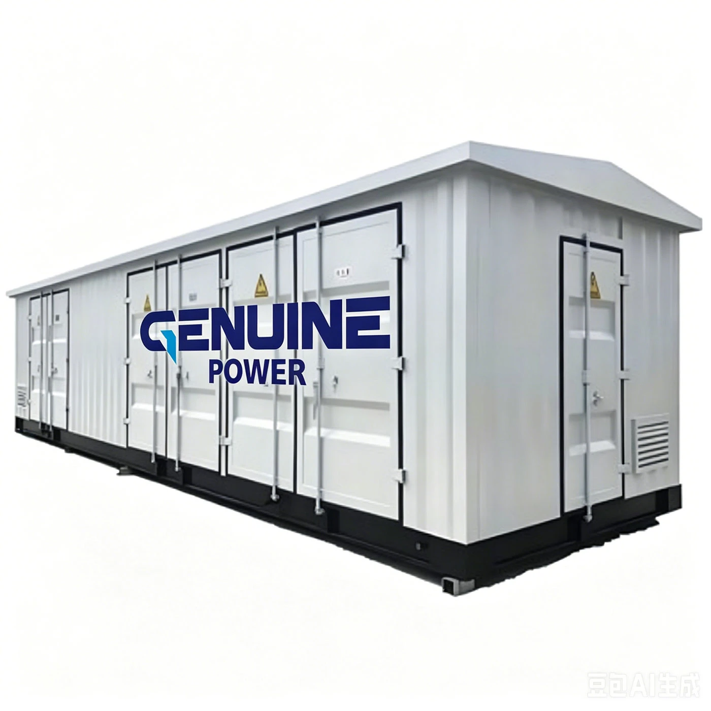
2. Core Functions of Capacitor Banks
Capacitor banks are widely used in low-voltage industrial power distribution systems to improve power factor, reduce reactive power losses, enhance power quality and achieve energy savings.
Their main functions include:
• Improving Power Factor
The capacitive reactive power generated by capacitors compensates for the inductive reactive power of the load, reducing the phase difference between voltage and current and effectively improving the system power factor.
• Reducing Line Losses and Preventing Overload
By reducing unnecessary reactive current in the system, the total line current decreases accordingly, which lowers power losses in cables and transformers and helps prevent overload caused by excessive reactive power.
• Stabilizing Grid Voltage
Heavy inductive loads often cause voltage drops and fluctuations, which may affect the normal operation of electrical equipment. Capacitor compensation helps stabilize terminal voltage and improve power supply reliability.
• Releasing Transformer Capacity
Reactive power occupies part of the transformer's rated capacity, limiting its ability to deliver active power. Reactive power compensation frees up transformer capacity and improves equipment utilization efficiency.
3. Cabinet Structure and Operating Characteristics
3.1 Main Components
A standard low-voltage capacitor bank mainly consists of:
- Cabinet enclosure
- Busbars
- Circuit breakers
- Isolating switches
- AC contactors
- Thermal relays
- Lightning arresters
- Compensation capacitors
- Series reactors
- Automatic power factor controllers
- Measuring instruments
- Primary and secondary wiring systems
- Terminal blocks
3.2 Operating Characteristics
The capacitor bank operates automatically under normal conditions and generally does not require routine manual intervention. It starts and stops together with the main power supply system.
The built-in intelligent controller continuously monitors load conditions and system power factor in real time. According to reactive power demand, it automatically switches capacitor banks on or off to maintain an optimal compensation state and minimize reactive power losses.
For routine maintenance, regular inspections should be carried out to check for:
- Capacitor oil leakage or swelling
- Abnormal noise or overheating
- Loose wiring connections
- Aging cables or damaged components
4. Hazards of Low Power Factor (Excessive Reactive Power)
If reactive power compensation is not installed in systems with large inductive loads, the power factor will decrease significantly, leading to the following problems:
- Higher line current increases thermal losses in cables and transformers, resulting in greater energy consumption and wasted electricity;
- Excessive voltage drop causes unstable and reduced grid voltage, which may affect the normal operation of electrical equipment;
- Reactive power occupies transformer capacity and limits available active power output, reducing the utilization efficiency of power distribution equipment.
5. Calculation Method for Required Compensation Capacity
Empirical Sizing Method for Industrial Applications
In practical engineering applications, the required compensation capacity is generally taken as roughly one-third of the transformer's rated capacity (unit: kVAR).
Depending on actual load characteristics and operating conditions, the compensation capacity is generally within a range of 30% to 40% of the transformer's rated capacity.
Example
For a 200 kVA distribution transformer:
Recommended compensation capacity:
200 × (30% ~ 40%) = 60 ~ 80 kVAR
Therefore, a capacitor bank with a capacity between 60 kVAR and 80 kVAR is generally recommended to meet on-site reactive power compensation requirements.