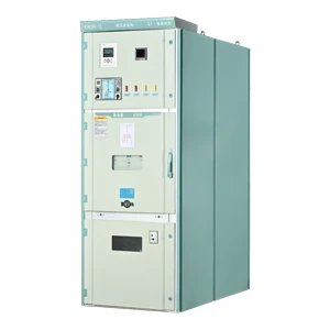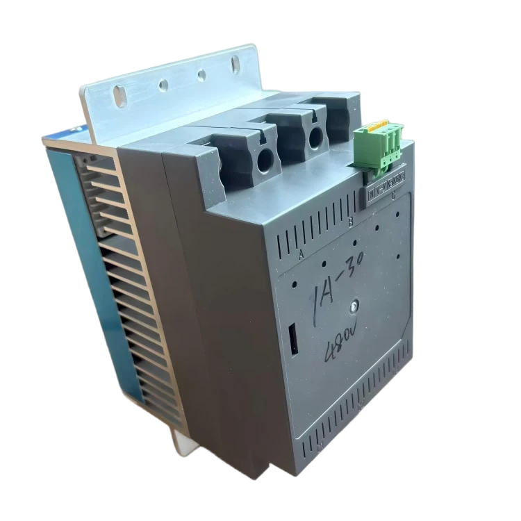

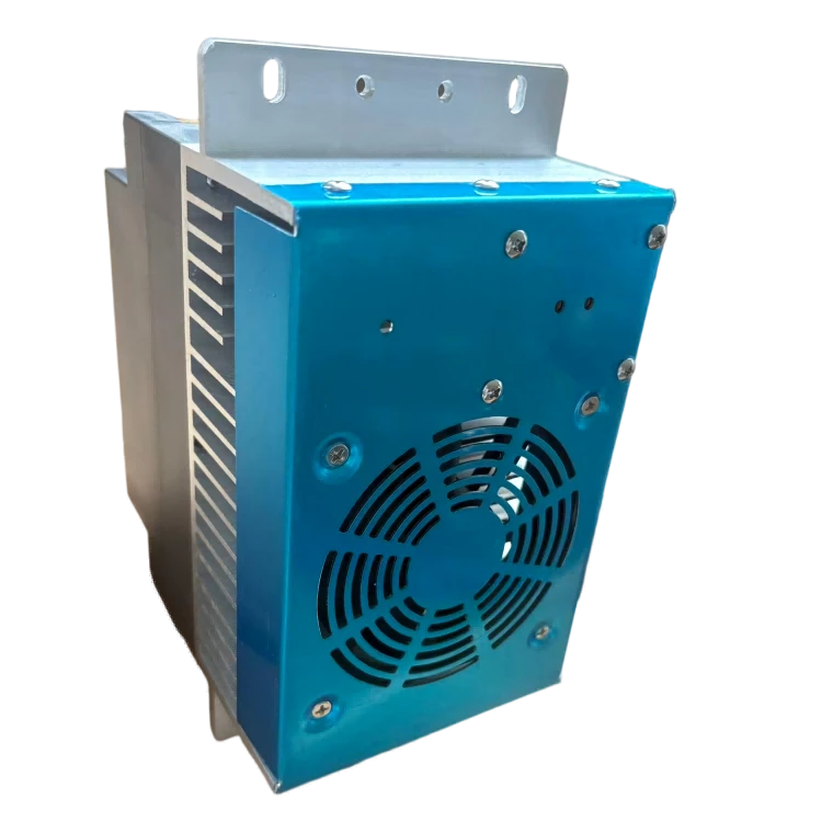
400V Low‑Voltage TSC Thyristor Contactless Switch
✅Fast switching speed, adaptive control signal
✅Superior heat dissipation, complete temperature protection, long service life
✅Universal installation design, suitable for harsh industrial environments
✅Complete model range, anti-harmonic design, stable and safe operation

- Product Introduction
The 400V Low‑Voltage TSC Thyristor Contactless Switch (commonly known as capacitive contactless switch) is a power device capable of fast switching of power capacitors. It is applicable to reactive power compensation control for occasions with rapidly varying loads, such as terminals, welding workshops, shipyards and steel rolling mills.
a. The 400V Low‑Voltage TSC Thyristor Contactless Switch is controlled by a DC 12V voltage signal (automatic positive and negative polarity adaptation).
b. LED indicators directly display the status of power supply, switching, fan, over-temperature, etc.
c. The control terminal of each switch is equipped with 2 common signal connection points to facilitate cascade wiring of multiple switches.
d. The mounting heights of large and small housings are compatible, and they can be installed on the same cross beam simultaneously.
e. Equipped with over-temperature protection function.
Technical Parameters
a. Voltage range: rated voltage -15% ~ +20%
b. Frequency range: 45–65 Hz
c. Control signal voltage: -12 V ±20% / 2 mA or +12 V ±20% / 2 mA
d. Primary response speed: <20 ms for all models
e. Secondary response speed: <80 ms for all models
f. SCR forward voltage drop: typical value 1.2 V
g. Fan starts at 45 °C, with an operating hysteresis of 5 K.
h. Overtemperature protection activates at 85 °C, with an operating hysteresis of 40 K.
Operating Conditions
a. Ambient air temperature: -25℃ ~ +40℃.
b. Altitude: not exceeding 1200 m.
c. The installation site shall have clean air, free of explosive and flammable hazardous materials; free of gases that may damage insulation or corrode metals; free of conductive dust; and protected from rain, snow and severe mould growth.
d. No significant harmonics at the installation location. Note: "No significant harmonics" means that when the voltage at the installation point is 1.1UN (UN stands for the rated voltage of the capacitor), harmonic content shall not cause the capacitor current to exceed 1.2 times its rated current.
e. Regardless of whether harmonics exist in the operating environment, an iron-core reactor shall in principle be connected in series at the output of the regulator. This helps improve the service life and reliability of the thyristor.
Precautions for Use
a. The capacity of the connected capacitor shall not exceed the maximum allowable range of the thyristor switch.
b. The switching indicator light may be dimly lit when no capacitor is connected.
c. To judge whether a switch works normally, it must be tested with a capacitor load.
d. The thyristor switch generates a large amount of heat during operation, so the capacitor cabinet shall be equipped with adequate heat dissipation. The power consumption of the whole capacitor cabinet can be estimated by the following formula:
W = (Ia+Ib+Ic) × 1V
W : Total power consumption of the capacitor cabinet (Unit: W)
Ia : Maximum compensation current of phase A of the capacitor cabinet (Unit: A)
Ib:Maximum compensation current of phase B of the capacitor cabinet (Unit: A)
Ic :Maximum compensation current of phase C of the capacitor cabinet (Unit: A)
Model Naming Rules
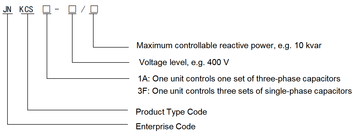
Available Models
| Available Models | Split Compensation | Common Compensation | Dimensions | Controllable Capacity | Connection Mode | Response Speed | Rated Voltage |
| JNK CS3F-20-3Y |  | Type S | 20K Var | 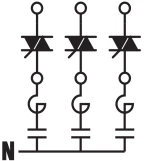 | 20mS | Phase230V | |
| JNK CS3F-30-3Y |  | Type S | 30K Var | ||||
| JNK CS3F-40-3Y |  | Type S | 40K Var | ||||
| JNK CS3F-50-3Y |  | TypeB | 50K Var | ||||
| JNK CS3F-60-3Y |  | TypeB | 60K Var | ||||
| JNK CS3F-80-3Y |  | TypeB | 80K Var | Phase400V | |||
| JNK CS3F-100-3Y |  | TypeB | 100K Var | Phase430V | |||
| JNK CS3F-100-3Y |  | TypeB | 100K Var | Phase460V | |||
| JNK CS1A-20-3 |  | Type S | 20K Var | 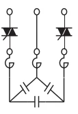 | 20-80mS | Line400V | |
| JNK CS1A-30-3 |  | Type S | 30K Var | ||||
| JNK CS1A-40-3 |  | Type S | 40K Var | ||||
| JNK CS1A-50-3 |  | Type S | 50K Var | ||||
| JNK CS1A-50-3 |  | TypeB | 50K Var | ||||
| JNK CS1A-60-3 |  | TypeB | 60K Var | ||||
| JNK CS1A-80-3 |  | TypeB | 80K Var | ||||
| JNK CS1A-80-3 |  | TypeB | 80K Var | 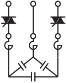   | Line690V | ||
| JNK CS1A-100-3 |  | TypeB | 100K Var | Line750V | |||
| JNK CS1A-100-3 |  | TypeB | 100K Var | Line800V |
① Switching time is less than 20 ms when no reactor is connected in series. If a reactor is connected in series, the switching speed depends on the discharge speed of the capacitor. The capacitor can be switched on once its residual voltage is lower than the peak value of the grid voltage, and the switching time is generally between 20 ms and 80 ms. When a reactor is connected in series, a discharge coil can be fitted to each switch if the user has requirements on response speed.
Installation Dimension Drawing
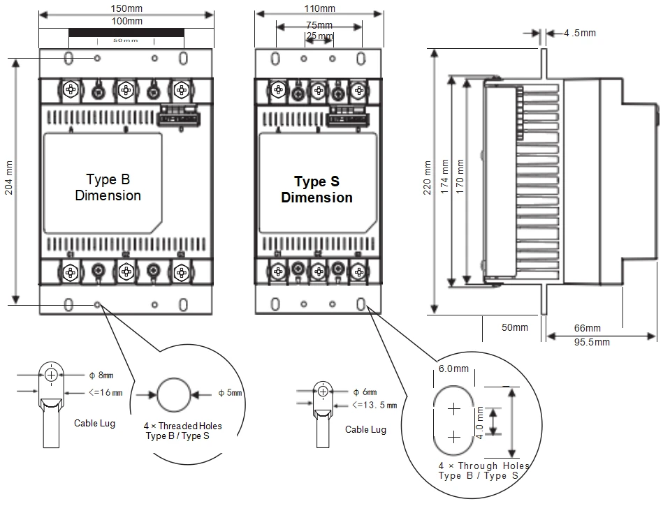
Use Proper Fastening Tools
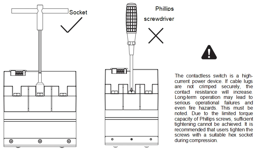
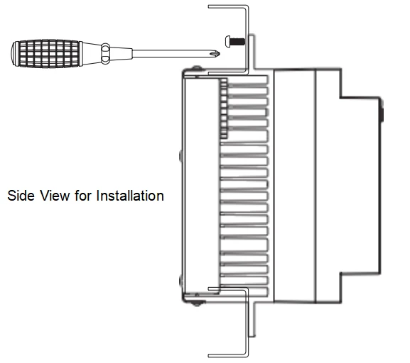
(Please use Φ5 combination screws supplied by the manufacturer)
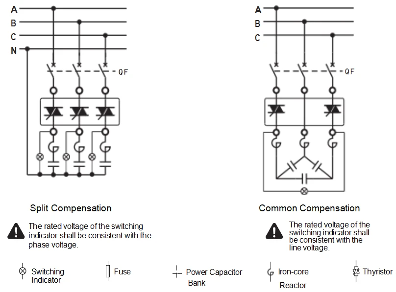
Primary Circuit Wiring Schematic Diagram
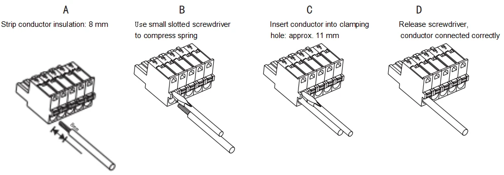
Correct Operation of Control Terminals
Secondary Circuit Wiring Schematic Diagram
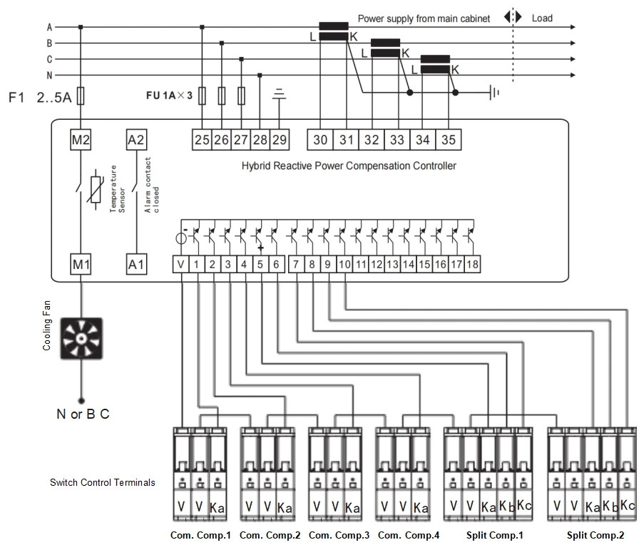
| Control Terminal No. | Common Compensation Type No. | Split Compensation Type No. | Terminal Function |
| V |   |   | Common terminal 1 of control signal is internally connected to common terminal 2. |
| V |   |  | Common terminal 2 of control signal is internally connected to common terminal 1. |
| Ka |   |   | Common compensation: switching control signal;Split compensation: Phase A switching control signal |
| Kb |   | Split compensation: Phase B switching control signal | |
| Kc |   | Split compensation: Phase C switching control signal |
Panel Functions

Common Compensation Contactless Switch Panel Diagram Split Compensation Contactless Switch Panel Diagram
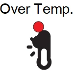
 Once the contactless switch triggers an "Over Temperature" alarm, the switching indicator light shall turn off immediately, and capacitor switching is prohibited.
Meaning of Panel Indicators
| Indicator Symbol |
|
|
| 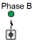 | 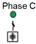 | 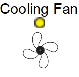 |  |
| Display Color | Green | Green | Green | Green | Green | Yellow | Red |
| Meaning of Lamp On | Power Normal | Common compensation capacitor switched on | Phase A split compensation capacitor switched on | Phase B split compensation capacitor switched on | Phase C split compensation capacitor switched on | Cooling fan is operating | The temperature of the radiator exceeds 85℃ |
| Meaning of Lamp Off | ① | Common compensation capacitor switched off | Phase A split compensation capacitor switched off | Phase B split compensation capacitor switched off | Phase C split compensation capacitor switched off | Cooling fan stopped operating | Radiator temperature within normal range |



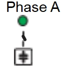
①: Off or flashing indicates that the power supply voltage is less than or close to 85% of the rated value. The switching function is disabled under low voltage condition.
Hot Tags: 400v low‑voltage tsc thyristor contactless switch, China 400v low‑voltage tsc thyristor contactless switch manufacturers, suppliers, factory