




Fault Analysis and Countermeasures of Switchgear
 Mar 13, 2026|
 What is Switchgear?
Switchgear is an assembly composed of one or more low-voltage switching devices and associated control, measurement, signaling, protection, regulation and other equipment.All internal electrical and mechanical connections are completed by the manufacturer, and it is fully assembled with structural components into an integrated unit.
Main Functions of Switchgear
During the processes of power generation, transmission, distribution and energy conversion in the power system, switchgear is used for switching, control and protection of electrical equipment.
Internal Components of Switchgear
Switchgear mainly consists of circuit breakers, disconnectors, load switches, operating mechanisms, instrument transformers, and various protective devices.
12~40.5kV switchgear is the most widely used primary substation equipment in power grid systems. In recent years, frequent accidents involving switchgear have caused economic losses, casualties, and other adverse social impacts.
Its accident hazards and inherent defects are mainly concentrated in aspects such as wiring configuration, internal arc release capability, internal insulation, overheating, and anti-error interlocking. By formulating targeted countermeasures, the number of accidents in switchgear and ring main units has been greatly reduced, and the reliability of power grid operation has been steadily improved.
1. Hidden Hazards in Wiring Configuration
1.1 Types of Hidden Hazards
1.1.1 Direct Connection of Surge Arresters to Busbars in TV Cabinets
According to the requirements of typical design specifications, surge arresters in TV cabinets must be connected to busbars via isolating hand trucks. However, due to the diverse compartment layouts and wiring configurations in TV cabinets, surge arresters in some TV cabinets are not connected to busbars through isolating hand trucks. When performing maintenance on the TV, the isolating hand truck is withdrawn, but the surge arrester remains energized, posing an electric shock risk to personnel entering the compartment for work. The main wiring configurations of surge arresters in TV cabinets are shown in the following figures:
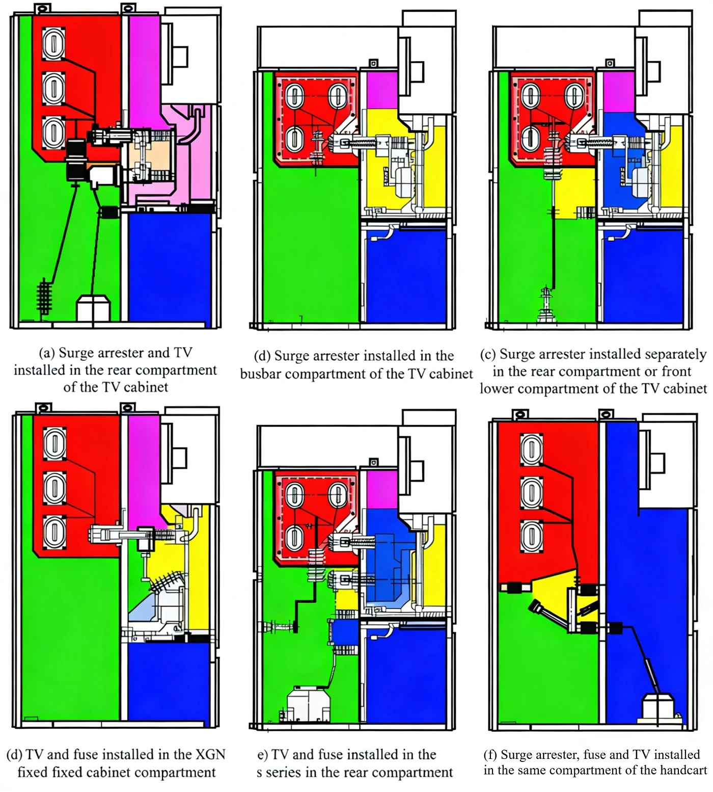
⑴.Wiring Method 1: The surge arrester and TV in the TV cabinet are installed in the rear compartment, the fuse is installed on the trolley, the surge arrester is directly connected to the busbar, and the TV is connected to the busbar through the isolating trolley.
⑵.Wiring Method 2: The surge arrester in the TV cabinet is installed in the busbar compartment, directly connected to the busbar, and the TV and fuse are installed on the trolley.
⑶.Wiring Method 3: The surge arrester in the TV cabinet is separately installed in the rear compartment or front lower compartment, directly connected to the busbar, and the TV and fuse are installed on the trolley.
⑷.Wiring Method 4: The TV and fuse are installed in the compartment of the XGN series fixed cabinet, and the surge arrester is separately installed in another compartment, directly connected to the busbar.
⑸.Wiring Method 5: The surge arrester, TV and fuse are all installed in the rear compartment, the surge arrester is directly connected to the busbar, and the TV is connected to the busbar through the isolating trolley.
⑹.Wiring Method 6: The surge arrester, fuse and TV are installed on the same trolley, and the surge arrester is connected after the fuse. This wiring method is incorrect. Once the fuse blows during operation, the equipment will lose the protection of the surge arrester.
1.1.2 The lower compartment and rear compartment of the switchgear are not fully isolated
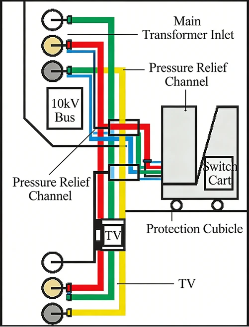
Some KYN series switchgear, including main transformer incoming line switchgear, busbar coupling switchgear, feeder switchgear, etc., have not achieved complete isolation between the lower compartment and the rear compartment. Staff entering the lower compartment may accidentally touch live parts such as busbars or cable heads, resulting in electric shock. The hidden danger of the incomplete isolation between the lower compartment and the rear compartment of the switchgear is shown in the figure.
1.2 Countermeasures
Carry out primary wiring reconstruction on switchgears with potential hazards in wiring configuration.The schematic diagram of the switchgear wiring reconstruction is shown in the figure:

1.2.1 Technical Retrofit Plan for Surge Arrester Wiring Methods in TV Cabinets
⑴.For Wiring Method 1: Remove the surge arrester inside the compartment, keep the TV wiring method unchanged, seal the original wall penetration hole in the busbar compartment, place the surge arrester on the trolley and retrofit it into a fuse-surge arrester trolley, and connect the surge arrester in parallel with the fuse and TV circuit.
⑵.For Wiring Method 2: Remove the surge arrester in the busbar compartment, move the surge arrester to the trolley and retrofit it into a trolley shared by the fuse and surge arrester, add a lower contact box mounting plate, contact box baffle and live door mechanism, install the TV in the rear compartment, and connect it to the lower contact of the isolating trolley through a lead wire. This plan can be implemented on the original trolley, or consider replacing with a new trolley.
⑶.For Wiring Method 3: Remove the surge arrester in the original compartment, move the surge arrester to the trolley and retrofit it into a trolley shared by the fuse and surge arrester, seal the original wall penetration hole in the busbar compartment, add a lower contact box mounting plate, contact box baffle and live door mechanism for the trolley, install the TV in the rear compartment, and connect it to the lower contact through a lead wire. This plan can be implemented on the original trolley, or consider replacing with a new trolley.
⑷.For Wiring Method 4: Remove the surge arrester inside other compartments, move the surge arrester to the compartment of the fuse and TV, connect it after the isolating switch break, and connect it in parallel with the fuse and TV circuit.
⑸.For Wiring Method 5: Keep the installation positions of the surge arrester and TV unchanged, connect the original surge arrester lead wire directly to the lower contact of the isolating trolley, and seal the original wall penetration hole in the busbar compartment.
⑹.For Wiring Method 6: This wiring arrangement is incorrect. Once the fuse blows during operation, the equipment will lose the protection of the surge arrester. Remove the surge arrester and fuse from the original trolley, change the wiring position to connect the surge arrester upstream of the fuse, and connect it in parallel with the fuse and TV circuit.
1.2.2 Preventive Measures for Incomplete Isolation Between Lower and Rear Cabinets of Switchgear
Since the product structure of such switchgears is finalized, installing partition plates during reconstruction will change their internal structure and spatial distribution, making it impossible to guarantee the internal protection performance.Therefore, before entering the cabinet for operation, it must be confirmed that the 10kV side of the main transformer and the main transformer circuit breaker have been switched to maintenance status before work can be carried out.
2. Internal Insulation Problems
2.1 Types of Hidden Hazards
In recent years, as the size of switchgears has continuously decreased, more defects and failures related to internal insulation performance have occurred. The main manifestations are:
● Insufficient creepage distance and air clearance. Especially in draw-out switchgears, many manufacturers have greatly reduced the phase-to-phase and phase-to-ground distances of circuit breakers and isolating plugs installed in the cabinets to shorten the cabinet size, without taking effective measures to ensure insulation strength.
● Poor assembly technology. Although individual components inside the switchgear can pass the withstand voltage test, the assembled switchgear cannot pass as a whole due to poor assembly quality.
● Insufficient contact capacity or poor contact. This causes local temperature rise and degraded insulation performance, leading to phase-to-ground or phase-to-phase flashover.
● Condensation. The built-in heater is prone to damage and failure, resulting in condensation inside the switchgear and reduced insulation performance.
● Poor insulation performance of auxiliary components. Some manufacturers use accessories with low insulation levels to reduce costs, lowering the overall insulation performance of the switchgear.
2.2 Countermeasures
Do not blindly pursue miniaturization of switchgears. Select appropriate switchgears based on engineering conditions, substation layout, operation, maintenance and equipment overhaul.
● For equipment using air or air/insulating materials as insulation medium, consider the thickness of insulating materials, design field strength and aging. Require manufacturers to conduct condensation tests in accordance with standards.
● For wall-through bushings, mechanical valves, busbar bends and other parts in switchgears and ring main units where the clear air insulation distance is less than 125mm (12kV) and 300mm (40.5kV), apply insulation sheaths to conductors.
● For areas with concentrated electric field strength such as incoming/outgoing bushings, mechanical valves and busbar bends, take measures such as chamfering and polishing to prevent electric field distortion.
Spray RTV insulating coating on insulating supports such as busbar insulators that cannot meet anti-pollution requirements, to improve the operating conditions of old equipment.
3. Incomplete Anti-misoperation Locking
3.1 Types of Hidden Hazards
Most switchgears are equipped with anti-misoperation locking devices, but their comprehensiveness and enforceability do not meet requirements.
The rear upper cabinet door of some armored switchgears is openable without anti-misoperation locking or double isolation baffles. Live parts can be directly touched after opening, and ordinary hexagon socket screws are used, leading to risks of electric shock due to unauthorized entry.
Some switchgears (main transformer, bus tie, TV, station transformer, etc.) without earthing switches have rear lower cabinet doors not mechanically interlocked with earthing switches. The door can be opened directly by removing screws, and closing power transmission is possible with the door open, causing risks of electric shock.
The upper and lower parts of the rear cabinet door of some switchgears (e.g., KYN28) cannot be locked independently. When the outgoing earthing switch is closed, both lower and upper rear cabinet doors can be opened, causing electric shock hazards.
After the draw-out truck is withdrawn, the insulation isolation baffle can be easily pushed up without anti-misoperation locking, exposing live parts and leading to electric shock risks.
3.2 Countermeasures
Install mechanical padlocks and microcomputer anti-misoperation program locks on high-voltage switchgears whose rear upper cabinet doors can be opened to directly access live parts.
Add interlocks between earthing switches and rear cabinet doors, and live display devices to lock earthing switch operation on GG1A, XGN and other switchgears.
Regularly check the reliability of anti-misoperation devices. Inspect mechanical interlocks between draw-out trucks and earthing switches, disconnectors and earthing switches during power outages.
4. Insufficient Internal Arc Release Capacity
4.1 Types of Hidden Hazards
Internal arc faults may occur in metal-enclosed switchgears due to inherent defects, deteriorated insulation under severe operating conditions, or misoperation.The arc generated by short circuit has high temperature and large energy. Driven by electrodynamic and thermal forces, the arc moves rapidly inside the cabinet and expands the fault scope.Insulating materials gasify, metals melt, and internal temperature and pressure rise sharply. Without qualified pressure relief channels, huge pressure may deform or rupture partitions, doors, hinges and observation windows.High-temperature gas ejected from the cabinet may cause severe burns or even fatal injuries to nearby operation and maintenance personnel.Current in-service equipment has problems such as no pressure relief channel, unreasonable layout, untested internal arc release capacity, and lax test assessment.
4.2 Countermeasures
Selection: Internal fault arc performance shall be IAC class, allowable duration ≥ 0.5s, test current equal to rated short-time withstand current. For products with rated short-circuit breaking current above 31.5kA, internal fault arc test can be performed at 31.5kA.
Reconstruction: Install or modify pressure relief channels, and verify internal arc performance in strict accordance with type test standards.
Protection: Appropriately reduce the protection coordination time margin of main transformer sections to shorten the duration of arc damage.
5. Heating Defects
5.1 Types of Hidden Hazards
Poor contact at circuit connections increases contact resistance and causes serious heating (e.g., poor contact of isolating contacts).
Unreasonable vent design of metal armored cabinets results in poor air convection and heat dissipation, leading to frequent internal heating.
Electromagnetic closed loops formed by installation structures of wall-through bushings, current transformers, etc., generate eddy currents and cause severe heating of isolation baffles.
Dry-type components (cast-type CT, VT, dry-type transformer) in some enclosed switchgears use insufficient winding wire gauge and poor casting technology, making them prone to overheating and damage.
5.2 Countermeasures
Improve heat dissipation by installing supply and exhaust fans.
Inspect contact pressure of fixed and moving contacts during power outages, replace worn parts and fatigued contact springs if necessary.
Strengthen research on internal temperature measurement technology, and apply new technologies such as wireless temperature monitoring to solve temperature measurement difficulties.