




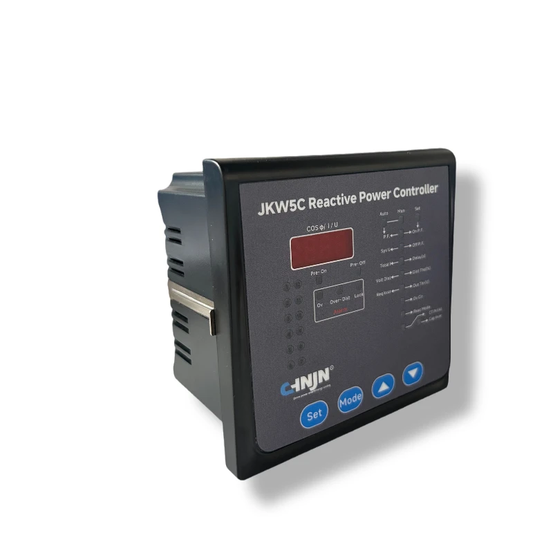

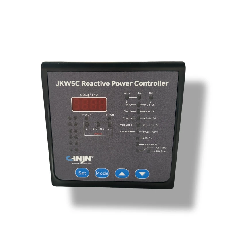
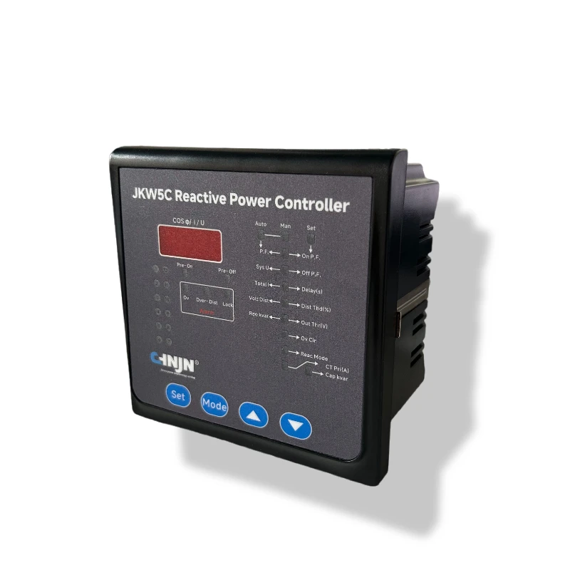
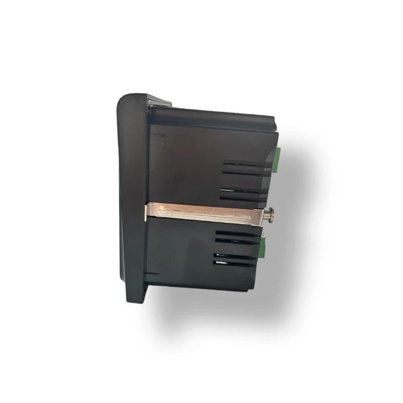
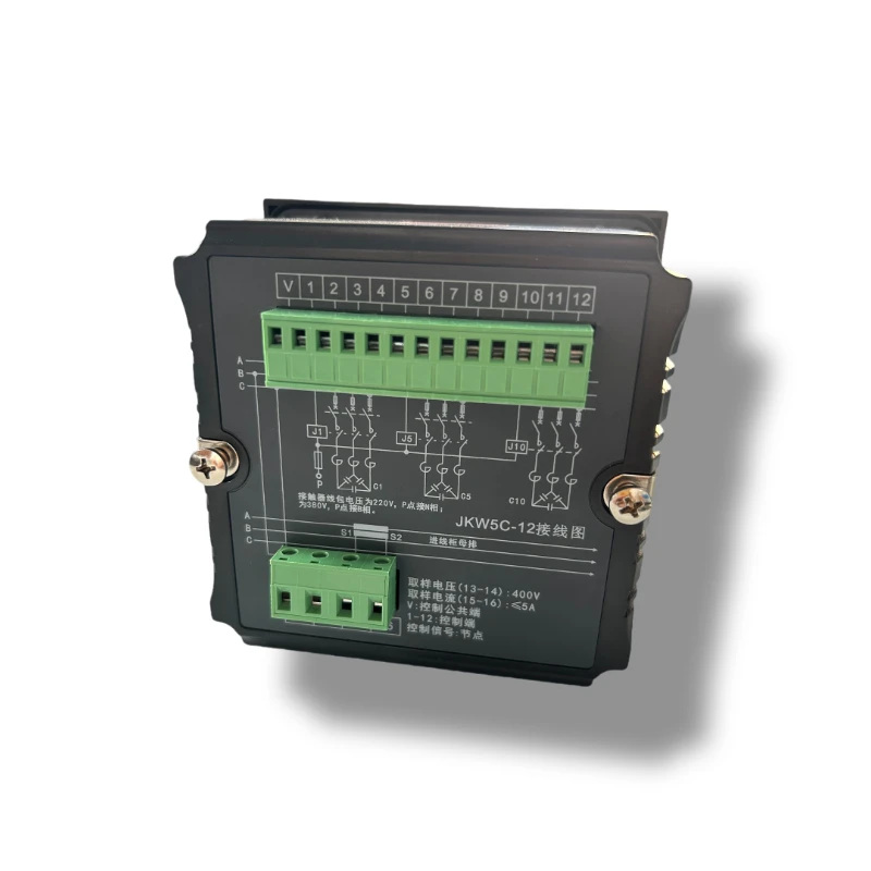
JKW5C Reactive Power Factor Regulator
✅Precise Reactive Power Compensation Control,Dynamic Response and various control modes
✅Energy Efficiency and Economic Benefits,improves power factor to above 0.95
✅Supports static compensation and dynamic compensation,hybrid compensation
✅Human-Machine Interface,real-time monitor power statu
✅Self-Diagnosis,Automatically detects issues and triggers alarms
✅Smart Protection:overvoltage,undervoltage,overcurrent,and overheating,with event logging for fault analysis

- Product Introduction
JKW5C Reactive Power factor regulator
Product Overview
Jinneng Electric's JKW5C Reactive Power factor regulator
is designed for reactive power compensation in low-voltage distribution systems. It monitors electrical signals and controls capacitor-bank switching according to the configured control strategy. The controller features automatic current-signal polarity recognition, anti-hunting lockout in power factor control mode, and harmonic measurement and protection functions. These features support commissioning, capacitor-switching control, and monitoring of relevant electrical conditions. For installations with significant harmonic distortion, the complete compensation system should be evaluated before selecting the capacitor bank and any additional harmonic mitigation equipment.
How It Work
The JKW5C Reactive Power factor regulator is designed to manage reactive power compensation in low-voltage power distribution systems. It monitors electrical signals, evaluates the system's power factor and reactive power demand, and controls capacitor bank switching according to the configured control parameters.The basic working process consists of the following steps: Electrical Signal Measurement → Power Factor Evaluation → Reactive Power Demand Analysis → Regulator Stage Selection → Regulator Switching → Power Factor Correction
1. Electrical Signal Measurement
The regulator receives voltage and current sampling signals from the power distribution system. These signals provide the electrical information needed to evaluate the system's operating conditions.2. Power Factor and Reactive Power Evaluation
Based on the sampled electrical signals, the controller evaluates the power factor and reactive power compensation requirements to determine whether capacitor switching is needed.3. Capacitor Stage Selection
When additional reactive power compensation is required, the controller selects an appropriate capacitor stage according to its configured switching strategy and the available capacitor bank capacity.4. Automatic regulator Switching
The controller sends switching commands to the corresponding switching devices to connect or disconnect capacitor stages. The switching process responds to changing load conditions and the system's compensation requirements.5. Power Factor Correction
By adjusting capacitor bank switching according to the measured electrical conditions, the JKW5C helps improve power factor and maintain appropriate reactive power compensation in low-voltage distribution systems.The JKW5C also features anti-hunting lockout in power factor control mode, which helps reduce repeated and unnecessary switching under fluctuating control conditions. Its harmonic measurement and protection functions provide additional support for monitoring and protecting low-voltage compensation systems, subject to the product's specified operating conditions.Note: The regulator operates as part of a reactive power compensation system. The final compensation performance depends on the controller configuration, capacitor bank capacity, load characteristics, switching devices, and overall system design.
Technical Specifications
| Parameter | Specification |
| Product Model | JKW5C |
| Product Type | Reactive Power factor regulator |
| Main Function | Reactive Power Compensation |
| Current Range | 0-5.5A |
| Rated Voltage | 230V Phase, 400V Line |
| Frequency | 50HZ |
| Output Contact Rating | 5A/220V/Loop |
| Measurement | Voltage/Current/Power Factor/ Reactive Power |
| Switching Control | Cyclic Switiching for equil-capacity stages; optimal switching for unequal-capacity stages |
| Communication | specify avaliable interface/protocol and optional communication version |
| Operating Temperature | -25°C ~ +40°C |
| Humidity | ≤ 50% at 40°C, ≤ 90% at 20°C |
| Switch Control Mode | Cyclic switching (equal capacity), Optimal switching (unequal capacity) |
| Installation | Panel-mount |
| Customization | OEM/ODM availability to be confirmed separately |
Controller LED Status Indicators
| LED Indicator | Meaning |
| Pre-engagement | Indicates that after a delay, the regulator will engage a capacitor. |
| Pre-disconnection | Indicates that after a delay, the regulator will disconnect a capacitor. |
| Overvoltage | the samples voltage exceeds the voltage threshold. the regulator will disconnect capacitors sequentially. |
| Over-distortion | the sampled voltage distortion rate exceeds the threshold. the regulator will disconnect capacitors sequentially. |
| Lockout | the regulator has detected repeated switching. it will stop engaging for 30minutes or until reactive power exceeds 1.3 of the oscillation threshold. |
| 1-12 Loop | indicates that the number of capactitor loops currently engaged (1-12) |
| Auto Mode | the regulator is operating in automotic mode. |
| Manual Mode | the regulator is in manual mode. Usev▲ to engage or ▼ to disconnect capacitors. |
| Settings | the regulator is in parameter adjustment mode. Control settings can be modified. |
Key Features and Benefits
1. Automatic Current Signal Polarity Recognition
The regulator automatically identifies the polarity of the current sampling signal, helping simplify on-site commissioning and reduce troubleshooting associated with current signal polarity issues. This function supports reliable power factor correction control.
Key Benefits:
* Simplified installation and commissioning
* Reduced troubleshooting related to polarity issues
* Improved control reliability
2. Anti-Hunting Lockout in Power Factor Control Mode
The anti-hunting lockout function helps suppress repeated and unnecessary capacitor bank switching caused by fluctuating control conditions around the target power factor. It supports more stable compensation control and helps reduce switching operations and associated wear on switching devices.
Key Benefits:
* Improved switching control stability
* Reduced unnecessary repeated switching
* Reduced wear on switching devices and potential maintenance requirements
3. Harmonic Measurement and Protection
Equipped with harmonic measurement and protection functions, the JKW5C helps monitor relevant harmonic conditions and provides corresponding protection support under specified operating conditions. These functions help users assess potential harmonic impacts on low-voltage reactive power compensation systems.
Key Benefits:
* Harmonic monitoring capability
* Enhanced protection support for compensation systems
* Improved awareness of power quality conditions
Applications & Problems Solved




The final configuration should be based on the actual system requirements and equipment compatibility.
Maintenance & Troubleshooting
Proper inspection and maintenance help support the reliable operation of an automatic power factor controller and its associated reactive power compensation system. The following checks provide general guidance for the JKW5C low-voltage power factor controller.
1. Check Voltage and Current Sampling Signals
Verify that the voltage and current sampling connections are installed according to the product wiring diagram. Incorrect or unstable sampling signals may affect power factor evaluation and capacitor switching decisions.For systems using current transformers (CTs), check the CT wiring, connection points, and current signal polarity according to the manufacturer's instructions.
2. Verify Control Parameters
If the controller does not respond as expected, check the configured control parameters against the actual power distribution system. Relevant settings may include the target power factor, switching delay, and other model-specific control parameters.Confirm that the settings are appropriate for the connected capacitor bank and switching devices before making adjustments.
3. Inspect Capacitor Switching Behavior
If capacitor stages switch repeatedly or the compensation system does not respond as expected, review the measured electrical conditions, load variations, control settings, and switching device status.The JKW5C includes an anti-hunting lockout function in power factor control mode. If a lockout indication appears, refer to the product manual to verify the operating conditions and the appropriate troubleshooting procedure.
4. Respond to Overvoltage or Harmonic-Related Indications
If an overvoltage or distortion indication appears, inspect the system operating conditions and consult the controller's operating instructions.Check the relevant voltage and harmonic measurements, connected capacitor bank configuration, and other equipment that may affect power quality. Where necessary, arrange for a qualified technician to assess whether additional corrective measures are required.
5. Follow Recommended Inspection and Safety Procedures
Inspect wiring connections, switching devices, and related compensation equipment in accordance with the manufacturer's maintenance recommendations and applicable electrical safety requirements.Before carrying out inspection, wiring changes, or maintenance, isolate the equipment from the power supply and follow the appropriate lockout and verification procedures. Work should be performed only by qualified personnel.
When Should Technical Support Be Contacted?
Contact the supplier's technical team if the controller continues to show abnormal indications, fails to switch capacitor stages as expected, or exhibits unexplained compensation behavior after the recommended checks.To help identify the issue, provide the controller model, a description of the symptoms, relevant display indications, wiring information, and available system measurements.
Important: The checks above are general maintenance guidance, not a substitute for the official JKW5C operating manual or a site-specific troubleshooting procedure. Always follow the product documentation and applicable electrical safety requirements.
FAQ
1. Do you offer OEM services for the JKW5C power factor controller?
OEM options may include product labeling, logo customization, and packaging, subject to the available customization scope and order requirements. Please contact our sales team to confirm availability, minimum order quantity, and lead time.
2. Do you provide ODM services for power factor controllers?
ODM requirements can be reviewed based on the requested functions, technical specifications, and product platform. Our team can evaluate the feasibility of your proposed customization and confirm the available options.
3. What information should I provide for an OEM or ODM inquiry?
Please provide your target market, intended application, required specifications, estimated order quantity, branding requirements, and any applicable certification requirements. Reference drawings or existing product specifications can also help us evaluate your request.
4. Is a power factor regulator the same as a capacitor bank?
No. The power factor regulator is the control device, while the capacitor bank is the compensation equipment. The controller determines when and how much capacitor capacity should be switched into the system.
5. Can Power Factor regulator improve power factor?
Yes. When properly selected and configured with an appropriate capacitor bank, an APFC controller can automatically control reactive power compensation to improve the system power factor.
6. How many regulator steps can an Power Factor control?
The number of control steps depends on the specific controller model. The available configuration should be selected according to the required compensation capacity and system design.
7. Can an Power Factor regulator be used in industrial applications?
Yes. Power Factor regulator are commonly used in industrial plants, manufacturing facilities, commercial buildings and low-voltage distribution systems.
8. Can an Power Factor regulator be used with harmonic filters?
The compatibility depends on the system configuration. In systems with significant harmonic distortion, the capacitor bank and harmonic conditions should be evaluated before selecting the compensation system.
9. How do I select an Power Factor regulator?
Selection should consider the system voltage, frequency, required compensation capacity, number of switching stages, current measurement method, target power factor and harmonic conditions.
About Jinneng
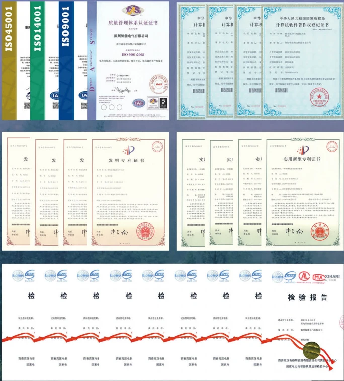
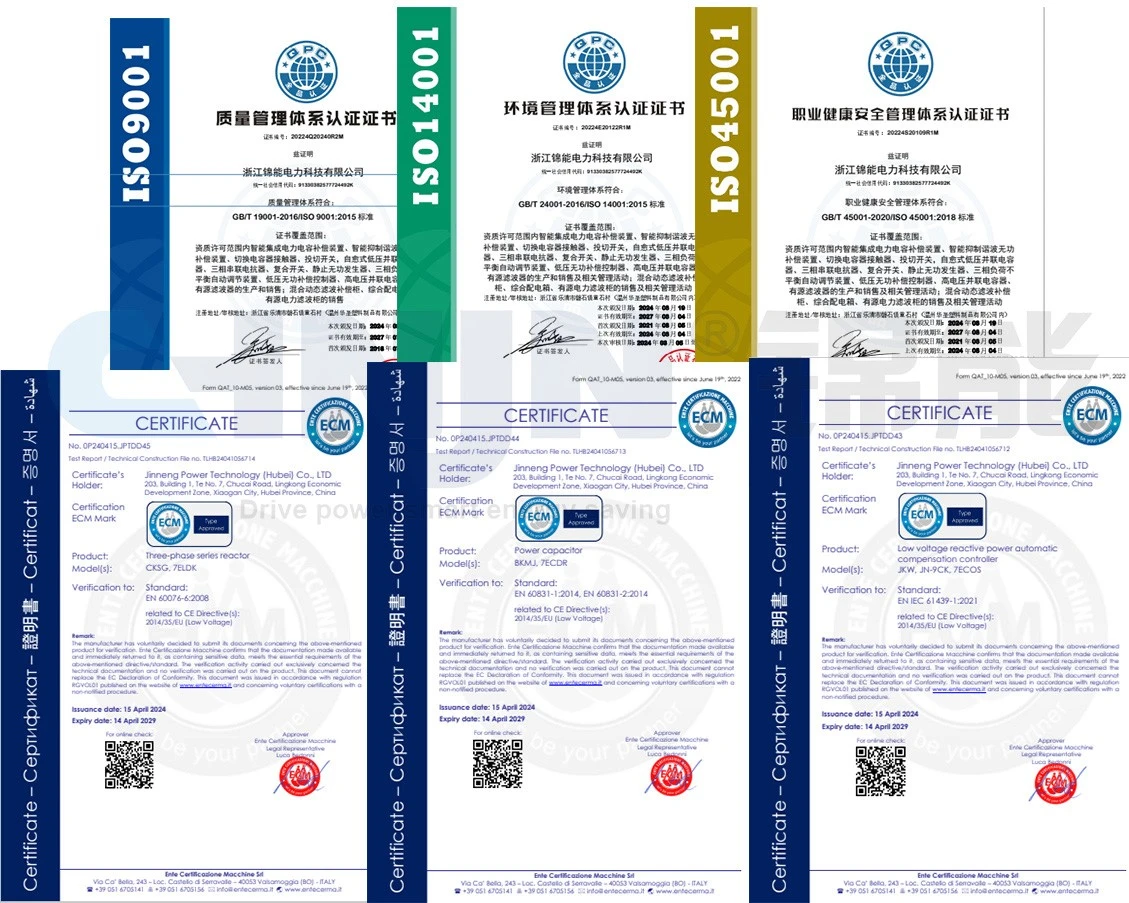
Jinneng electric power technology (Hubei) Co.,Ltd was founded in 2011, now located in Xiaogan City, Hubei Province, currently covers an area of more than 27,000 square meters, construction area of more than 43,000 square meters, the registered capital is 80 million, there are 28 engineers which belong to top R&D team, and had passed ISO9001, ISO14001, OHS18001, CCC, CQC, CE,IEC(TUV Rheinland) and other certifications.

01
Business partners
State Grid, China National Energy Construction, China Nuclear Photovoltaic, China Railway, Hong Kong MTR, Siemens, CATL, Tianneng battery etc.
02
Powerful R&D team
we have a strong r&d team, led by 3 professor / Dr, they lead 28 experienced engineers, focusing on research in cutting-edge technologies and innovative applications development, get breakthrough in the field of multiple technology, is committed to providing customers with leading power solutions.
03
Strong capital support
total registered capital of more than 200 million, equipped with modern production base in Hubei and zhejiang province.
Three divisions three series of products: electrical components, cable accessories, assembled electrical equipment, which can meet your one-stop purchasing needs, and save manpower and material resources cost.
04
Professional Sales Support
Our professional sales team provides responsive support, product selection guidance, and efficient communication to meet customers' needs.
Certifications & Quality Assurance
Quality and compliance are important considerations in electrical equipment selection. Jinneng provides relevant product documentation and certification information to support customer evaluation and project requirements.Available certificates, test reports, and technical documents can be provided for verification, subject to the specific product model and applicable standards.Please contact our team if you require certification documents or technical compliance information for your project.
Partner
Our partners are: State Grid, South grid, Three Gorges China, China National Energy Construction, Tianneng China Nuclear Photovoltaic(CNNC), PetroChina, China Railway, Hong Kong Metro,Siemens, etc.

Hot Tags: jkw5c reactive power factor regulator, China jkw5c reactive power factor regulator manufacturers, suppliers, factory


