




Beginner’s Guide to Capacitor Compensation Cabinet Components & Schematics
 Sep 19, 2026|
 A Reactive Power Compensation Cabinet (or Power Factor Correction Cabinet) automatically adjusts power factor, reduces energy losses, and stabilizes system voltage. Understanding the physical appearance, schematic design, and function of its main internal components makes panel inspection and electrical schematic reading simple and intuitive.

1. Physical Appearance & Functions of Core Components
⚡Power Capacitor (Designation: Capacitor / C)
- Visual Identification: A cylindrical or square metal enclosure featuring a printed rating label on the casing. Key parameters like rated capacitance (e.g., 30 kvar) and operating voltage (e.g., 450V) are clearly stamped on the front.
- Primary Function: Supplies capacitive reactive power to offset inductive motor loads, raising the overall power factor of the system.
🌀Detuned Reactor (Designation: Reactor / L)
- Visual Identification: A heavy rectangular or toroidal unit equipped with magnetic iron-core or air-core copper/aluminum windings. Marked with a specific tuning reactance rate (e.g., 7% for 5th harmonics or 14% for 3rd harmonics).
- Primary Function: Suppresses high-frequency harmonic currents and prevents resonance, protecting power capacitors from overheating and early failure.
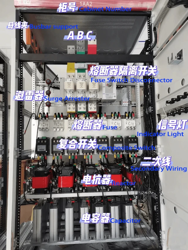
🔌 Fuse Switch Disconnector (Designation: QFD / FU)
- Visual Identification: A two-part modular assembly containing tubular high-rupturing capacity (HRC) fuse links mounted inside a hinged isolator body with an integrated operating handle.
- Primary Function: Serves as a main power isolation point for maintenance and delivers fast-acting short-circuit and overcurrent protection.
🔀 Composite Switch (Designation: Composite Switch / K)
- Visual Identification: A solid-state switch unit featuring a prominent extruded aluminum heat sink. It combines internal thyristors (SCRs) and magnetic latching contactors.
- Primary Function: Enables zero-crossing (inrush-free) capacitor switching to eliminate voltage spikes, minimize contact wear, and extend equipment operational lifespan.
🛡️ Surge Arrester (Designation: Surge Arrester / SPD)
- Visual Identification: A compact blue or black cylindrical body fitted with a dedicated grounding terminal at its base.
- Primary Function: Clamps transient overvoltages (such as lightning strikes or grid switching surges) to protect sensitive panel electronics.
💡 Panel Pilot Light (Designation: Pilot Light / HL)
- Visual Identification: A door-mounted LED indicator lamp, color-coded for quick visual diagnostics (e.g., Red = Running/Energized, Green = Stopped/Disengaged).
- Primary Function: Gives instant real-time visual feedback on individual capacitor branch switching status and system fault alarms.
2. Component Layout & Electrical Schematic Reading Tips
Understanding physical placement makes reading panel layouts and single-line diagrams (SLDs) much easier:
📍 Incoming Power Section
- Fuse Switch Disconnector: Located at the top tier of the enclosure, wired directly to the main incoming power busbars.
- Surge Protection Device (SPD): Mounted adjacent to the incoming line terminals and connected in parallel with the main bus.
📍 Compensation Branches
- Each individual capacitor step runs through a series connection:

- Current Transformers (CTs) and branch Pilot Lights monitor line current draw and indicate status per branch.
📍 Control & Monitoring Section
- Reactive Power Controller: Door-mounted microcomputer unit that senses total grid power factor and triggers secondary control logic for each step.
- Miniature Circuit Breakers (MCBs): Provide short-circuit protection for control wiring and fan power circuits.
3. Frequently Asked Questions (FAQ)
How do you identify whether a capacitor bank is currently switched ON or OFF?
Quick Answer: You can verify active switching status using three simple panel checks:
Check the Door Panel Indicator: Look at the pilot lights for that specific branch-a Red light usually indicates an active/running step, while a Green light shows the branch is disengaged.
Inspect the Composite Switch: Look at the mechanical status window or LED indicator directly on the composite switch module (marked "ON / OFF" or "RUN").
- Check the Controller Interface: Look at the digital screen on the main controller panel-active steps are typically displayed as highlighted numbers (e.g.,1 2 3 4)