




What is reactive power compensation, and how is the compensation amount calculated?
 Feb 02, 2026|
 In daily work, do you often encounter this question: the capacity of transformers is measured in kilovolt-amperes (kVA), the output power of motors in kilowatts (kW), and the power of capacitor compensation in vars or kilovars (var). Why are there three different terms for units that all represent electrical power?
This leads us to the topic we will discuss today: the inherent relationship between reactive power (unit: var or kvar), active power (unit: W or kW), apparent power (unit: VA or kVA), and the power factor.
I. In the power grid, the electrical power supplied by the source to the load can be categorized into two types: active power and reactive power.
(1) Reactive Power (Q):
Many electrical devices operate based on electromagnetic induction principles, such as distribution transformers and motors. Motors require the establishment and maintenance of a rotating magnetic field to drive the rotor, which in turn drives mechanical motion. The rotor's magnetic field in a motor is generated by drawing reactive power from the power source.
Transformers also require reactive power to generate a magnetic field in the primary winding and induce voltage in the secondary winding. Therefore, without reactive power, motors would not rotate, transformers could not transform voltage, and AC contactors would not engage. Generators can produce reactive power, and capacitors can supply reactive power-this is the basis of reactive power compensation.
(2) Active Power (P):
Active power refers to the portion of electrical power that can be directly converted into other forms of energy and consumed. For example, a motor converts electrical energy into mechanical energy. Without considering efficiency, an 11 kW motor can convert 11 kWh of electrical energy into an equivalent amount of mechanical energy per hour. A 100 W incandescent lamp converts 0.1 kWh of electrical energy into light energy per hour. Similarly, a 1 kW heater converts 1 kWh of electrical energy into thermal energy per hour. Active power is the electrical power that can be directly transformed into other forms of energy.
(3) Apparent Power (S):
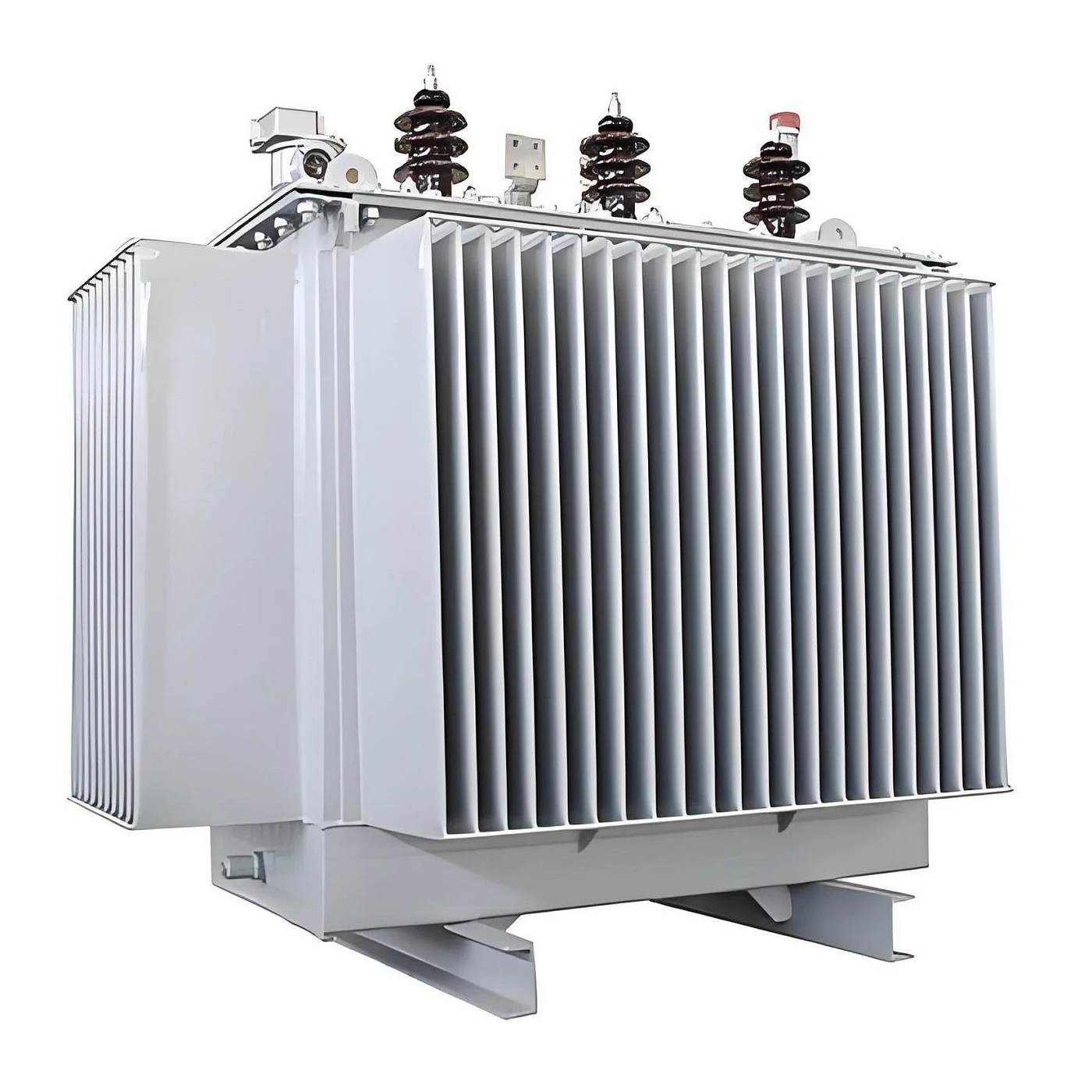
In a sense, apparent power is the combination of active power (P) and reactive power (Q). For power sources, apparent power comprises both active and reactive power. For instance, the power supplied by a transformer includes both active and reactive components, which is why the capacity of transformers is expressed in apparent power, measured in kilovolt-amperes (kVA).
II. The Relationship Among Active Power, Reactive Power, and Apparent Power
To explain the relationship among these three, we must first understand what the power factor is.
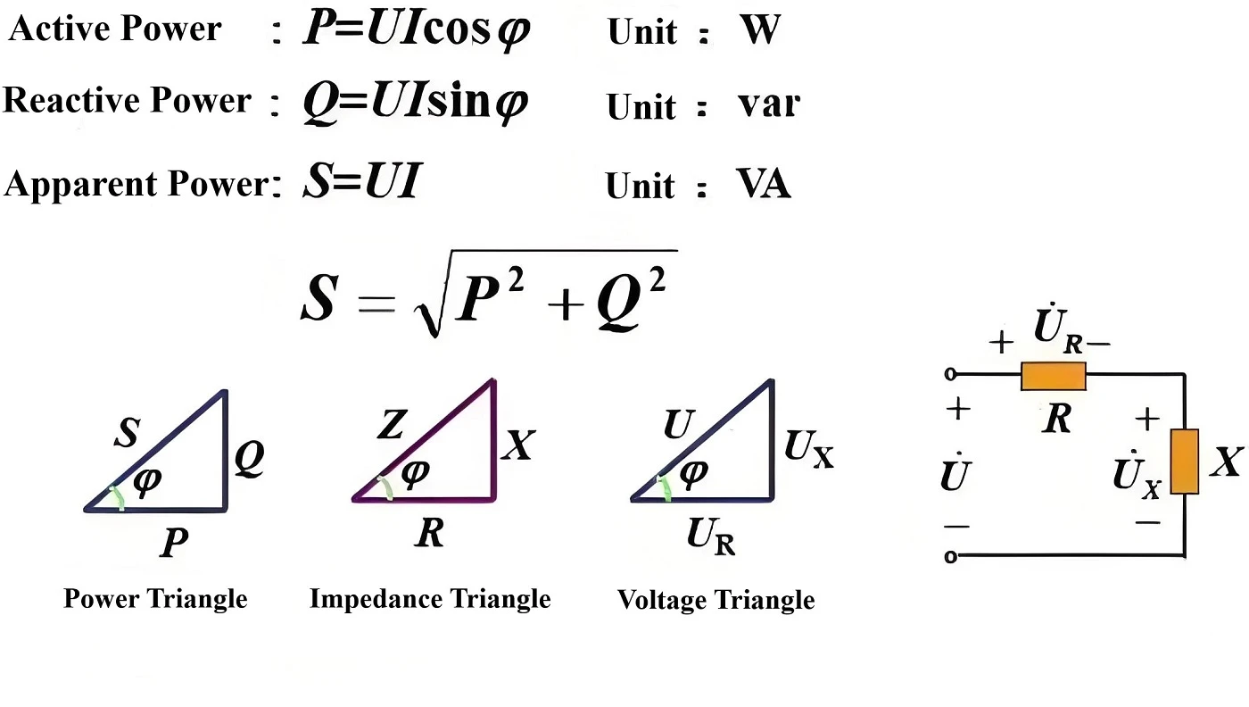
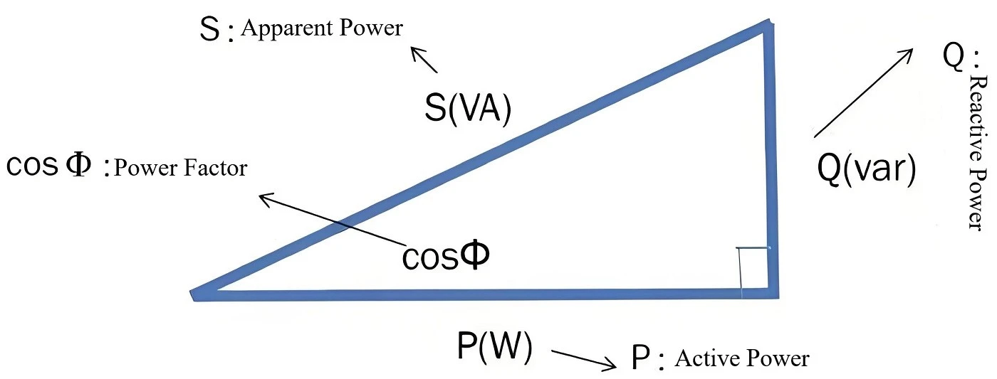
In an AC circuit, the cosine of the phase difference (Φ) between voltage and current is called the power factor, denoted as cosΦ. Numerically, the power factor is the ratio of active power to apparent power, i.e., cosΦ = P/S.
(1) What exactly is reactive power?
Based on the relationships illustrated by the power triangle, voltage triangle, and impedance triangle, reactive power can be simply understood in practical terms as follows:
In an electrical circuit, purely resistive components consume active power (P), while inductive components (such as reactor coils, transformer windings, and motor stators or rotors) consume reactive power (Q). On the other hand, capacitive components supply reactive power (Q) - for example, capacitors and synchronous generators. (Note: When a synchronous generator is operating, its windings behave capacitively, meaning it supplies both active power and reactive power.)
Thus, a simple summary is:
Inductive or capacitive components are the consumers and providers of reactive power.
(2) What are the negative impacts of reactive power?
Reduces the active power output of generators
This is because the total capacity (i.e., apparent power S) of a generator is fixed. If too much reactive power Q is supplied, the active power P will decrease accordingly; otherwise, the generator may overload.
Reduces the power supply capacity of transmission and distribution equipment
The rationale is the same as that for generators.
Increases line voltage losses
As the reactive current component in the circuit increases, the total current also increases. The voltage drop (δU = IZ) is proportional to the current. Larger voltage drops necessitate increasing the cross-sectional area of the conductors, leading to higher investment costs.
(3) The benefits of reactive power
Many electrical devices operate based on electromagnetic induction principles, such as distribution transformers and motors.
Motors require the establishment and maintenance of a rotating magnetic field to drive the rotor, which in turn drives mechanical motion. The rotor's magnetic field in a motor is generated by drawing reactive power from the power source.
Similarly, transformers need reactive power to create a magnetic field in the primary winding, thereby inducing voltage in the secondary winding.
Therefore, without reactive power:
Motors would not rotate,
Transformers could not transform voltage,
AC contactors would not engage.
From this, it is clear that reactive power plays a supporting role in the conversion and transformation of electrical energy. Without reactive power, magnetic fields cannot be established, and electrical energy cannot be converted into mechanical energy.
III. How to Perform Reactive Power Compensation and Calculate the Compensation Amount?
Above, we have analyzed the roles and drawbacks of reactive power together. The main drawbacks are: first, it increases the capacity of transformers and the cross-sectional area of conductors, which indirectly raises project costs; second, after operation, the power factor must not fall below 0.9, otherwise the power supply company will impose fines.
Therefore, during engineering design, we must fully consider this issue. In power supply systems without generators, parallel capacitors are typically used to improve the power factor of substations. The principle is to locally supply reactive power, eliminating the need to draw reactive power from the grid. This approach not only reduces the required capacity of transformers but also improves the power factor on the metering side.
(1) Selection of Capacitor Compensation Methods
1.When using shunt power capacitors as artificial reactive power compensation devices, to minimize line losses and voltage drops, compensation should be balanced locally. This means reactive power in low-voltage sections should be compensated by low-voltage capacitors, while reactive power in high-voltage sections should be compensated by high-voltage capacitors.
If there is no high-voltage load, shunt capacitor devices should not be installed on the high-voltage side.
When performing local individual compensation for motor-powered equipment, the rated current of the compensation capacitor should not exceed 0.9 times the motor's excitation current.
During electrical load calculations, the compensated reactive power should be included.
2.The switching modes for compensation capacitor banks are divided into manual and automatic.
Manual switching is suitable for capacitor banks compensating for basic low-voltage reactive power, as well as high-voltage capacitor banks with stable reactive power demand and infrequent switching.
To avoid over-compensation or excessive voltage during light loads, which could damage certain electrical equipment, automatic switching is recommended.
If the effects of high-voltage and low-voltage automatic compensation devices are similar, low-voltage automatic compensation devices should be preferred.
3.Regulation methods for automatic reactive power compensation:
For compensation aimed primarily at energy savings, parameters such as reactive power can be used for regulation.
For impact loads, dynamically fast-changing loads, and three-phase unbalanced loads, thyristors (electronic switches) can be employed for control, ensuring smooth operation without inrush currents, providing good dynamic performance, and enabling phase-segregated control for three-phase balancing effects.
4.When grouping capacitors, compatibility with the technical parameters of supporting equipment should be ensured. The allowable range of voltage deviation must be met, and efforts should be made to reduce the number of groups while appropriately increasing the capacity of each group.
Switching of grouped capacitors should not induce resonance.
5.High-voltage capacitor banks should preferably be connected in series with appropriately sized reactors, while low-voltage capacitor banks should increase switching capacity using dedicated switching contactors or thyristors to reduce inrush currents during switching.
On lines significantly affected by harmonics from electrical equipment, reactors should be connected in series with the capacitor banks.
(2) Calculation of Capacitor Compensation Capacity
The objective is to determine the required reactive power Qc (kvar) to

